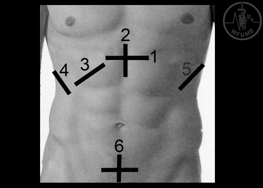
Fig 5.1
Overview over the 6 stations where the scanhead is positioned on a torso.
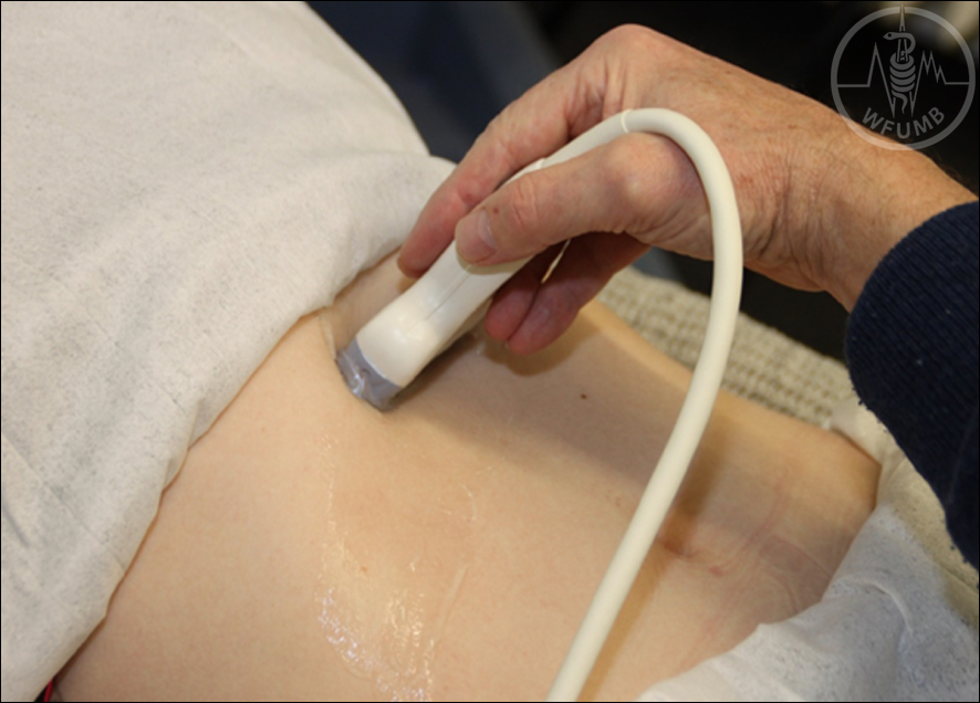
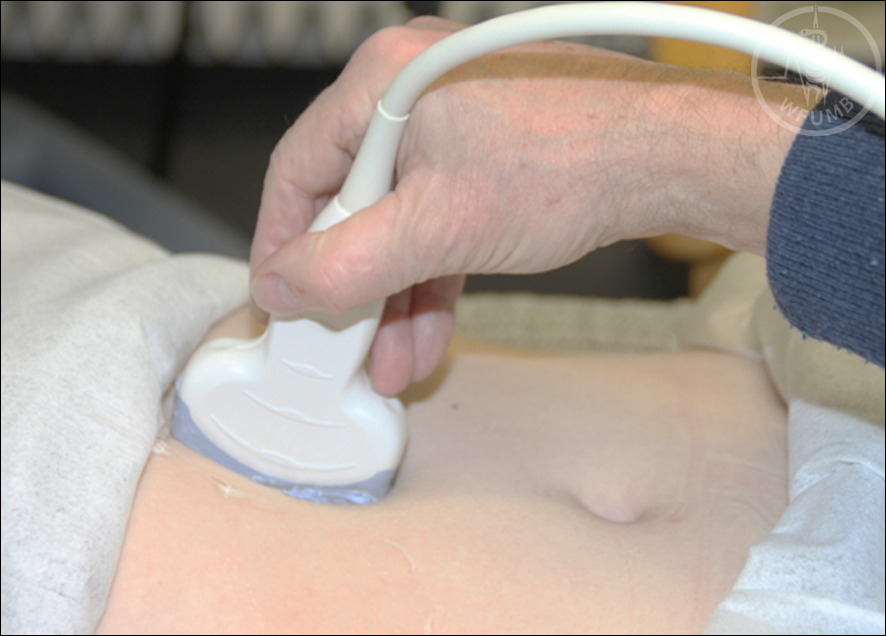
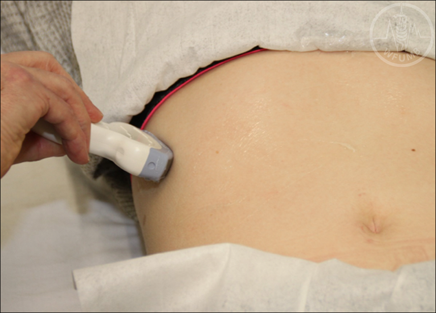
Fig 5.2
An illustration of probe placement in Station 1. The probe is placed in the epigastrium, below the xiphoid process in a horizontal plane.
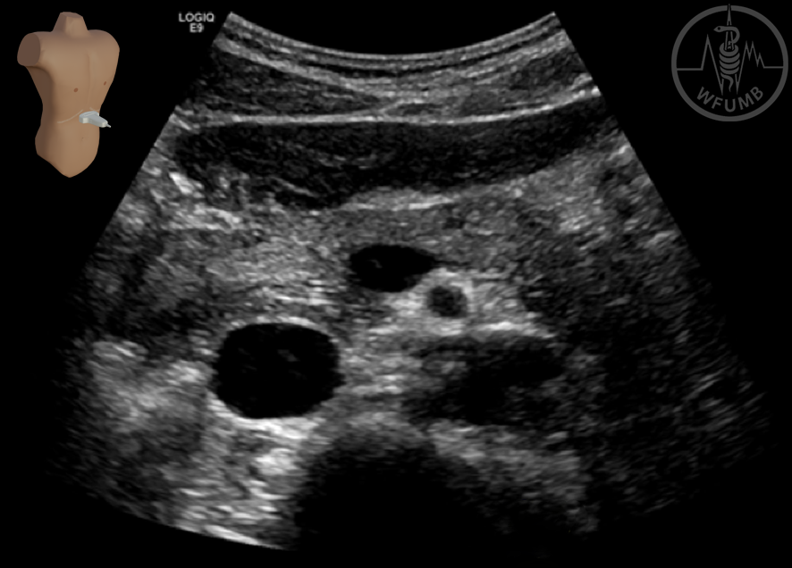
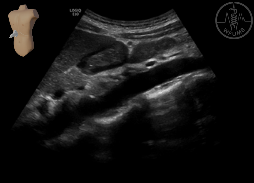
Fig 5.3
An overview of Station 1. The abdominal aorta and the cava vein are seen centrally in the picture. Just anterior to the aorta, the superior mesenteric artery is visible. The confluence between the splenic vein and the inferior mesenteric vein is seen posterior to the pancreas right next to the SMA. The left lobe of the liver is visible just anterior to the pancreas.
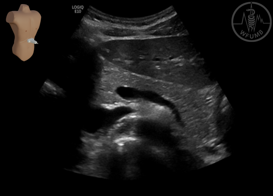
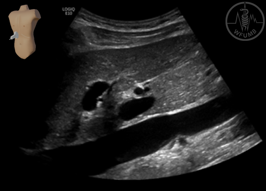
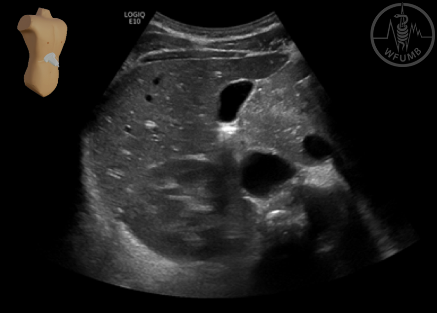
Fig 5.4
This image shows the left lobe of the liver, the body and part of the tail of the pancreas and the splenic vein with the confluence
Fig 5.5
An illustration of probe placement in Station 2. The probe is rotated 90 degrees clockwise from the horizontal section in Station 1, to a sagittal section.
Fig 5.6
A longitudinal plane of the aorta acquired from Station 2. The gastric antrum is seen in a transversal section.
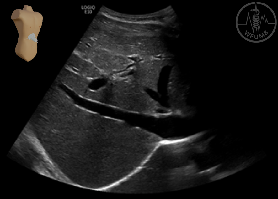
Fig 5.7
A longitudinal section of the cava vein. The liver, the portal vein and the pancreatic head are also visualized.
Fig 5.8
An illustration of subcostal probe placement in Station 3
Fig 5.9
In this image the right lobe of the liver is seen from Station 3. Hepatic vessels are visible inside the liver with the right and middle hepatic veins seen most distinctly.
Fig 5.10
The right lobe of the liver viewed from Station 3. A medium-filled gallbladder is seen just above the centre of the image. The right kidney in a transverse section is visible posterior to the liver.
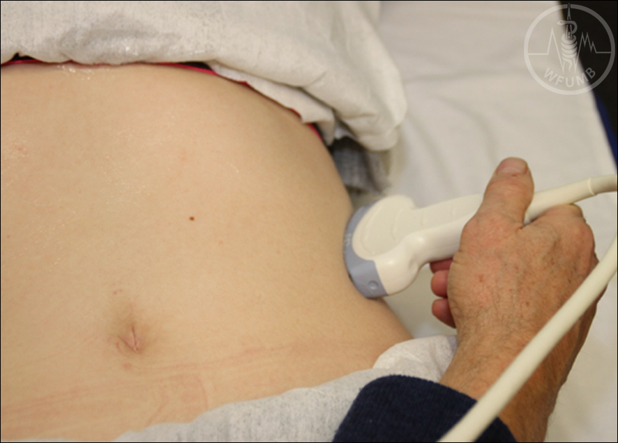
Fig 5.11
An illustration of probe placement in Station 4. The probe is placed in an intercostal position.
Fig 5.12
An image of the right kidney and the liver acquired from Station 4. A shadow from a costa is visible centrally in the image. To the right in the image, the gas-filled right colonic flexure is observed.
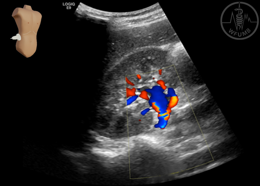
Fig 5.13
The central vessels of the kidney highlighted with colour Doppler.
Fig 5.14
An illustration of probe placement in Station 5. The probe is placed in an intercostal position; behind the mid-axillary line to view the normal-sized spleen.
Fig 5.15
The image shows the spleen acquired from Station 5. The length of the spleen is indicated between the two measurement points (yellow crosses).
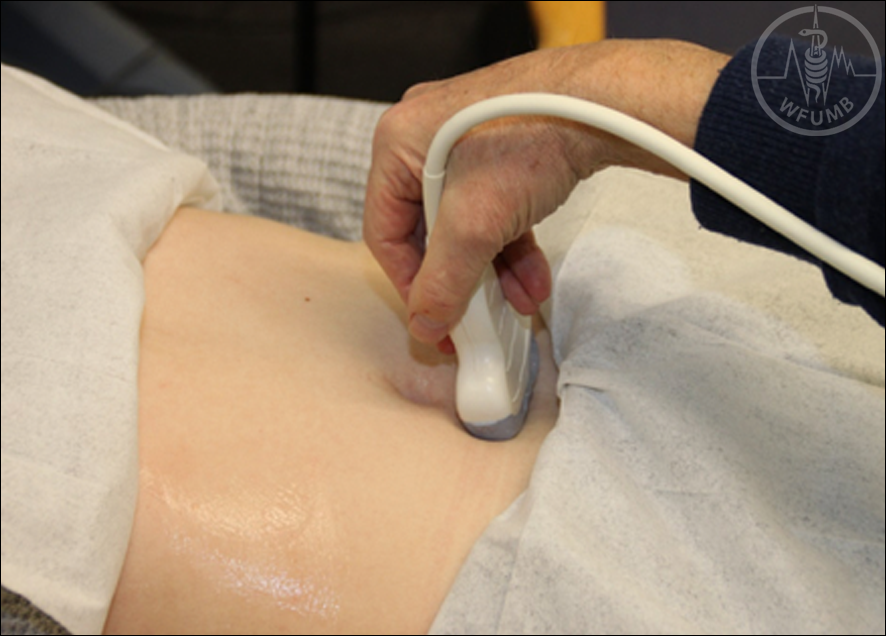
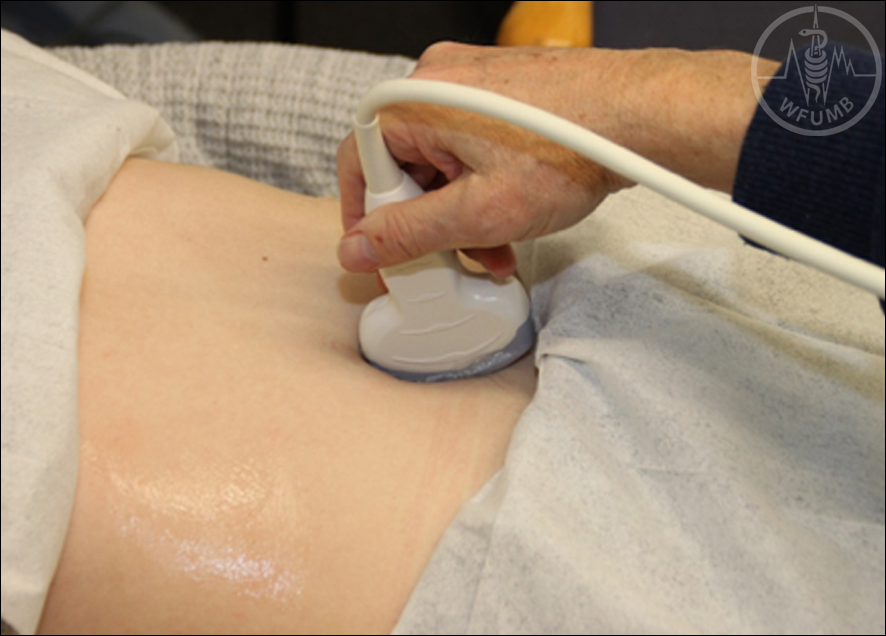
Fig 5.16a
An illustration of probe placements in Station 6, showing both a transverse and a sagittal section.
Fig 5.16b
An illustration of probe placements in Station 6, showing both a transverse and a sagittal section.
Fig 5.17
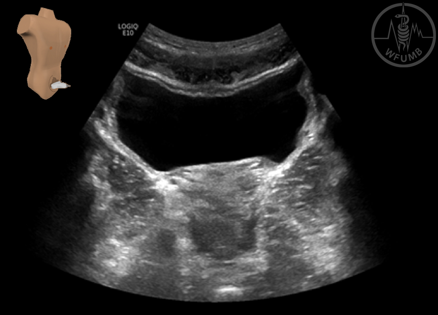
An image of the urinary bladder in a transverse plane.
Fig 5.18
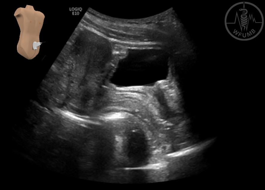
The urinary bladder and the uterus in a sagittal section. The body of the uterus is visible superior (to the left in the image) to the bladder, and the vagina is seen posterior to the bladder. The rectum with some gas is visualized posterior to the vagina
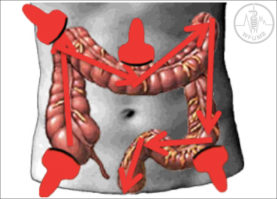
Fig 5.19
Illustration of the path of the probe for investigation of the large intestine. The transducer is moved from the right iliac region and tracks the colon distally to
the rectum
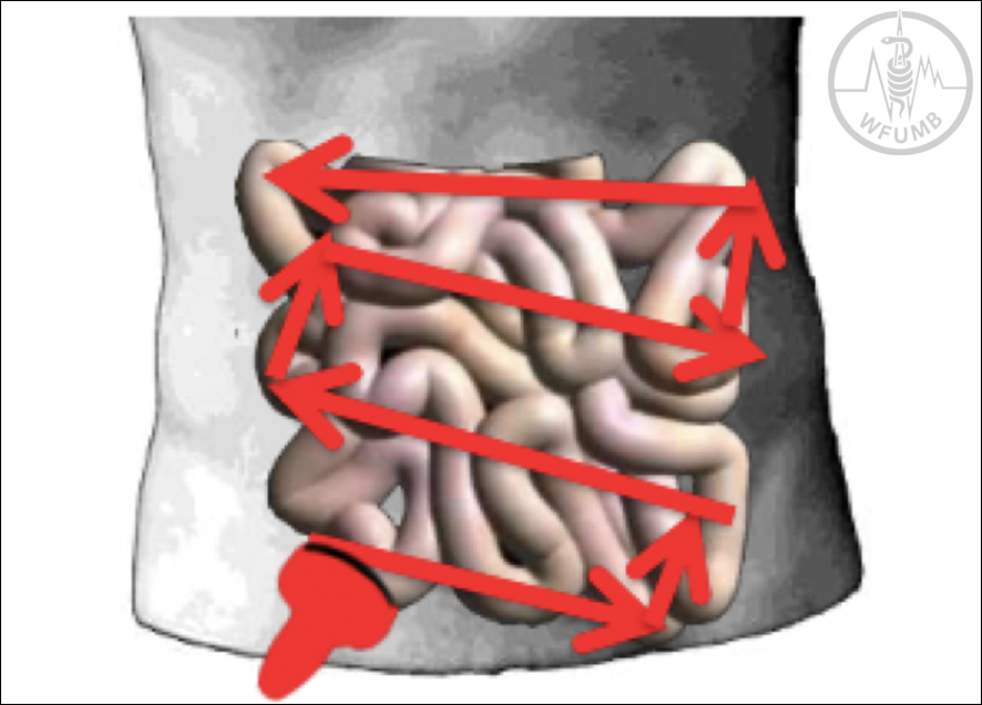
Fig 5.20
Illustration of the sweep path of the transducer while investigating the small intestine. Starting at the right iliac region, the transducer is moved upwards in a back-and-forth motion (“mowing the lawn”), covering as much of the small intestine as possible