Fig 25.1
MI and TIS will be listed on the screen and will change depending on presets
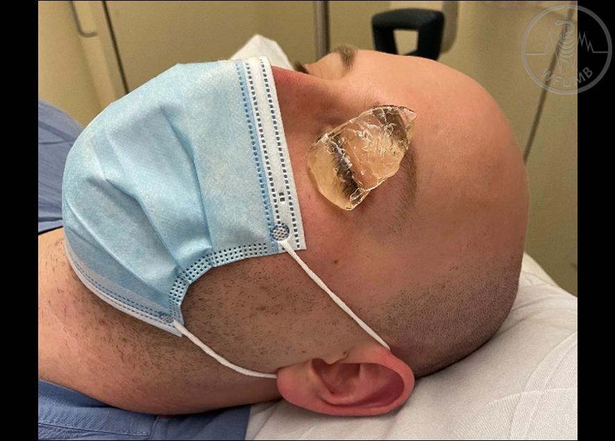
Fig 25.2
Apply a large amount of ultrasound gel or similar conducting media over the closed eyelid
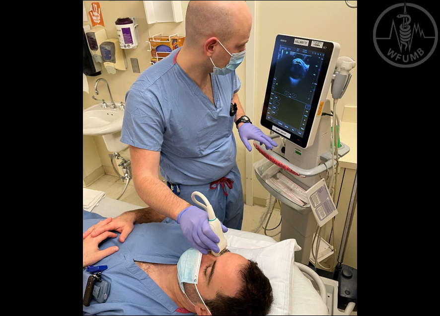
Fig 25.3a
Sonographer on the patient’s right, traditional head of the bed facing technique. Dominant hand rests on the patient’s cheek or nose
Fig 25.3b
Right handed sonographer on patient’s left, foot of the bed facing technique. Non-traditional but more stable
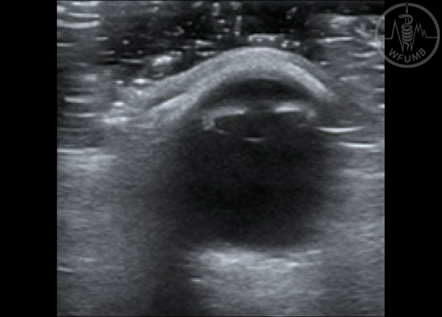
Fig 25.4
Pupil visualised from a slightly oblique angle. Notice the layer of gel in the near field to ensure minimal pressure on the globe
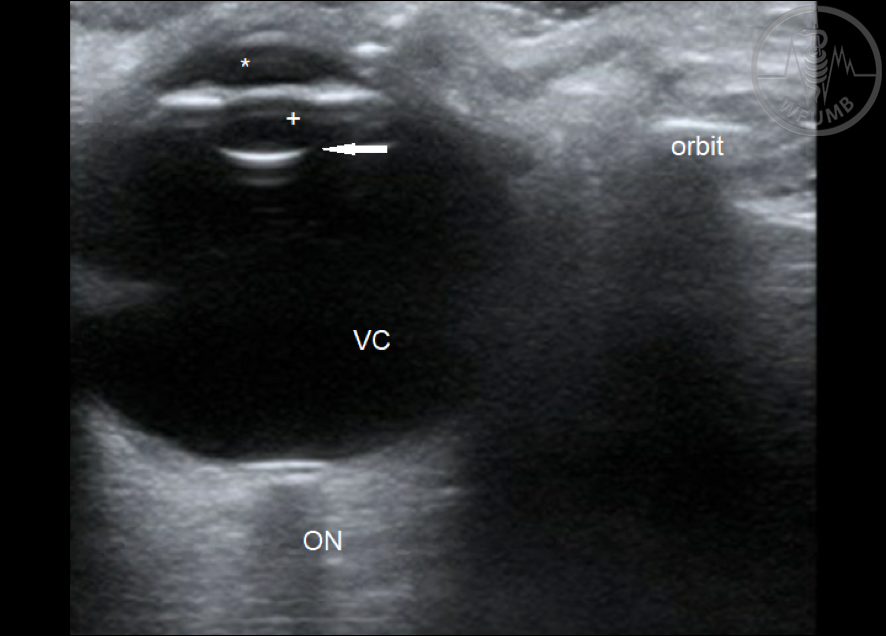
Fig 25.5
Ocular Sonoanatomy- From anterior to posterior: Anterior Chamber(*), Iris and Pupil, Posterior Chamber (+), Lens (arrow), Vitreous chamber (VC), Optic disc, Optic nerve (ON). A hyperechoic stripe with posterior shadow is seen to the right of the image indicating the orbital rim
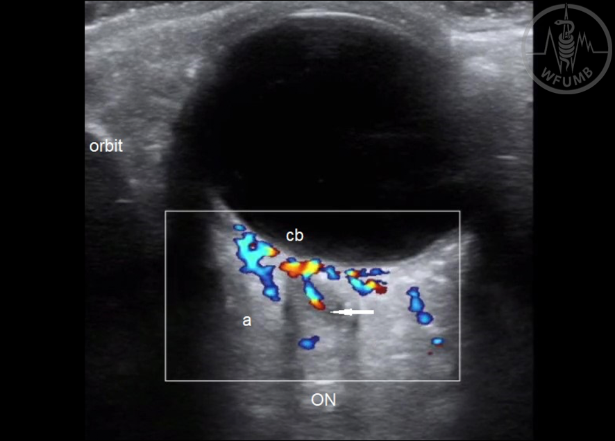
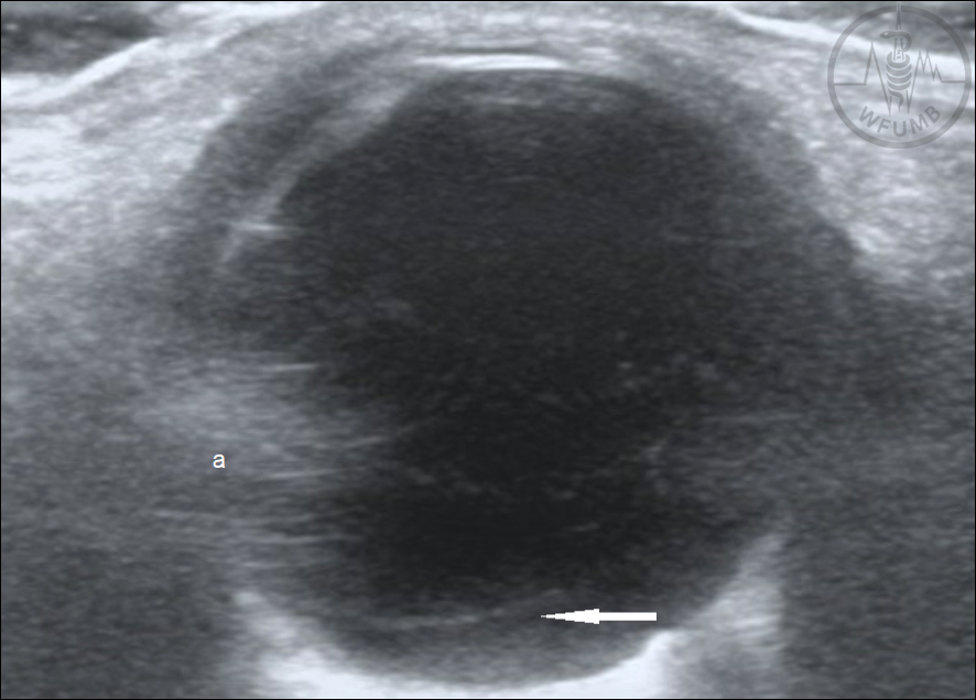
Fig 25.6
Anatomy of extra-bulbar structures. Hyperechoic bony orbit with posterior shadow noted along with hyperechoic retrobulbar fat (a), optic nerve (ON), central retinal artery and vein (arrow), and ciliary branches (cb)
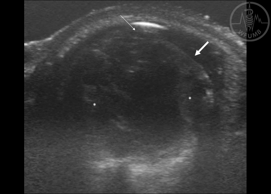
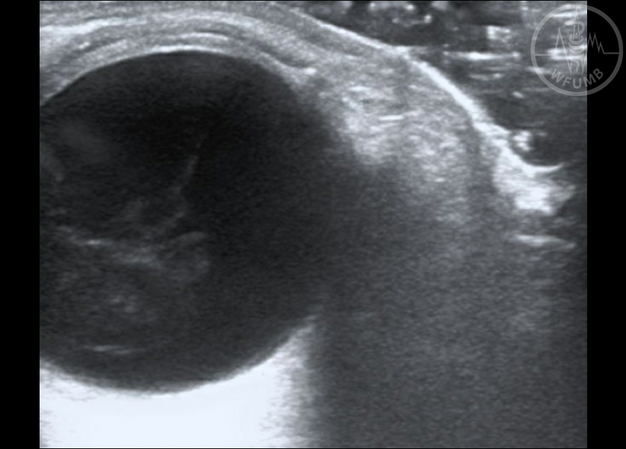
Fig 25.7
Globe Rupture with deformed anterior chamber (thin arrow), globe deformation (thick arrow), and hemorrhage (*). Note the presence of gel layer visualized in the near field to ensure limited pressure is put on the injured globe
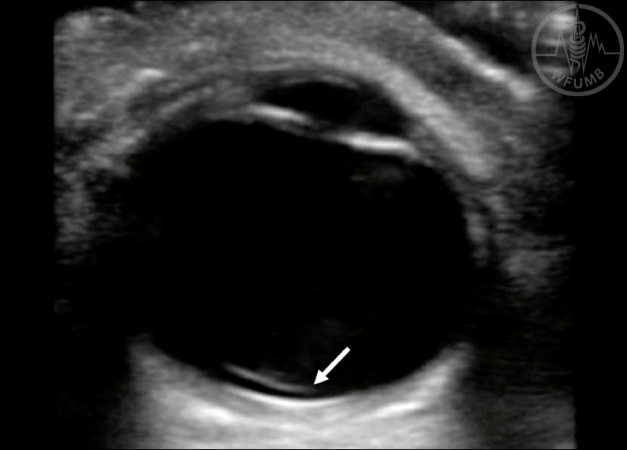
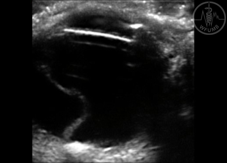
Fig 25.8
Lens dislocation (arrow)
Fig 25.9a
Retinal detachment with apex attached to optic nerve
Fig 25.9b
Vitreous detachment. Thin layer (arrow) crosses over optic nerve and not tethered. Multiple artifacts can also be seen (a)
Fig 25.10
Vitreous hemorrhage. Notice layering hyperdense material in vitreous chamber